The need
I had written a rendering framework long time back to realize that it doesn’t scale well when multiple passes get introduced. Everyone had heard of Frostbite’s presentation of Rendergraph, but I had never got a chance to look at it from an implementation standpoint. The next company I joined gave me that chance. It took me a while but figured out the flow, thanks to some sound documentations. Recession gave me the chance to get back to the drawing board and rewrite the rendering framework (every time I look at my old code it feels like a big load of junk). So, let's get to the design.
Design
The Rendergraph implementations which I came across mostly had a single pipeline throughout the entire application runtime, they either lacked the option for introducing a cut scene (Frostbite has this option) or they somehow modified the current pipeline during runtime and resulting in a re-compilation.
The current implementation can have multiple Pipelines, each of which can contain multiple Effects (opaque, transparent, SSAO, etc). Each of these effects can be implemented in multiple ways called Technique. The implementation chosen at runtime is based on the level of detail. Hence, an Opaque effect can be implemented by using a simple Lambertian lit or PBR technique and at runtime the objects closer to the camera will get PBR and the further ones will get the cheaper Lambertian lit.

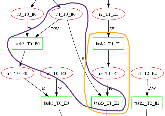
The Rendergraph manager handles all the pipelines. At runtime, a pipeline switch will be possible, allowing to maybe introduce a cut scene with different style of rendering. The CompilePipeline is responsible for creating the Rendergraph which is visualized using Graphviz (the first image). Each pipeline has its own graph, which is passed on to all the child containers (Effect, Technique). So, Pipeline contains Effect, Effect contains Technique and Technique contains TaskNode and ResourceNode.
The basic elements of the graph are TaskNode (green rectangles) and ResourceNode (red ovals), which will be explained later. These basic elements are added to the graph and inter-connected only by a Technique. A Technique can have open ends (resource or task nodes) to which other Techniques can connect. The responsibility of making such connections lie with parent Effect. An Effect can also have open ends to which other effects can connect and these connections are handled by the parent Pipeline.

The RenderGraphNodeBase is the base class for the nodes of the graph. The two categories of nodes are ResourceNode and TaskNode. ResourceNode represents any resource which might be used by TaskNodes. Textures and Buffers are the two types of resources. A single resource might travel through multiple tasks, hence the physical resource creation and destruction is handled by Technique once and then the tasks are connected to the multiple instances of the single physical resource using unique ResourceNodes. The state change management of resources is a work in progress. Resource class, representing the physical resource, acts as the base class for the BufferResource and ImageResource.
The second category of nodes in the graph is TaskNode. It encapsulates the Task class, which represents the actual work that is to be submitted to the GPU. Task class acts as the base class for RenderTask, ComputeTask, TransferTask and BlitTask. The names are self-explanatory but a note about BlitTask, it’s also used to blit the result of the pipeline to Swapchain images hence marking an end of a frame.
Implementation
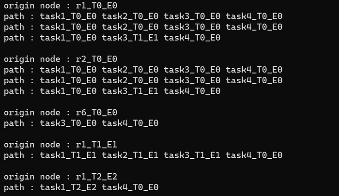
The whole purpose of the Rendergraph is to get a flat array of tasks with temporal dependencies intact. There are two major parts of this algorithm. First: traverse depth-wise through graph to get all the possible paths from the graph’s multiple origins to the single end. Please note there are 3 Effects E0, E1, E2 with respective Techniques namely T0, T1, T2.
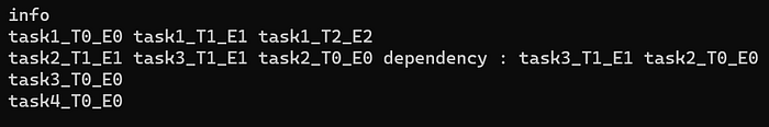
The arrays are iterated to segregate the tasks based on levels. A level for a task can be considered as the number of edges from the origin to the task. The result looks like below. During insertion, the current node is compared with the existing nodes in the level to check for dependency. There is a dependency between task2_T0_E0 and task3_T1_E1 as the read should happen before the write (purple shape in dependency image). In such a case, the insertion happens at specific location in the array, based on the usage parameter of the resource (R > RW > W) or else it’s a simple push_back.
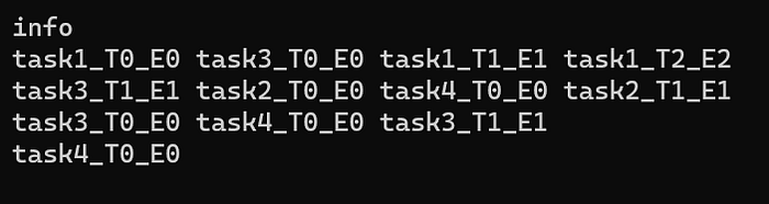
This level wise segregation allows us to reorder render passes for optimizations. This segregated task array of arrays is used as input for the second part of the algorithm.
Second: this part deals with task reorganization based on dependencies between them.
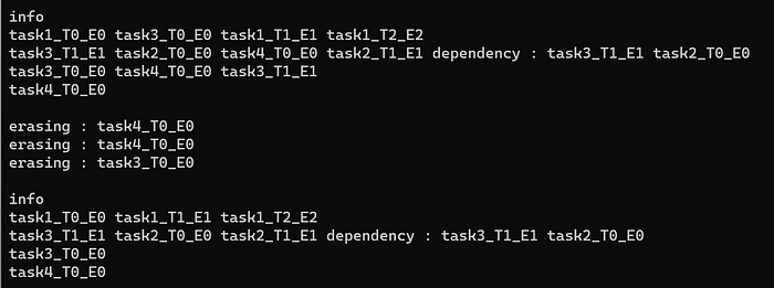
The level wise array of arrays is iterated in reverse order. So, starting from level3 (moving towards level0), the task is inserted into a flat array of tasks, if it doesn’t already exist. If it does, check for the dependency within the same level with other tasks.
In case there is no dependency in same level, erase the item from the current level. Task task4_T0_E0 is already in flat array, when iterating through level2, task4_T0_E0 gets knocked off from level2.
In case there is a dependency within the level, the task is removed from all the higher levels. Task task2_T0_E0 should proceed task3_T1_E1, hence when iterating through level1, task3_T1_E1 which already exists in the flat array, gets knocked off from the higher level level2.
Now all the duplicate tasks have been removed, but there is still some work left. Take a look at level1 after erasure. Task task3_T1_E1 is coming before task2_T1_E1, the dependency image above shows the dependency between these two tasks with the yellow shape. Hence, the last piece of this puzzle is to sort the tasks within the level if there is a common node between the inputs and outputs of the respective tasks. Here r3_T1_E1 is the common resource node between these tasks. The result of this sort is below.
The next stage of implementation is to iterate through the tasks and implement the various synchronization types in Vulkan and record the command buffers. Ah yes, this is a Vulkan renderer.

References:
Render graphs and Vulkan — a deep dive — Maister’s Graphics Adventures (themaister.net)
GDC Vault — FrameGraph: Extensible Rendering Architecture in Frostbite
Diplomarbeit Designing a Modern Rendering Engine